Slenderness Effects for Concrete Columns in Sway Frame - Moment Magnification Method
Slenderness Effects for Concrete Columns in Sway Frame - Moment Magnification Method
Slender Concrete Column Design in Sway Frame Buildings
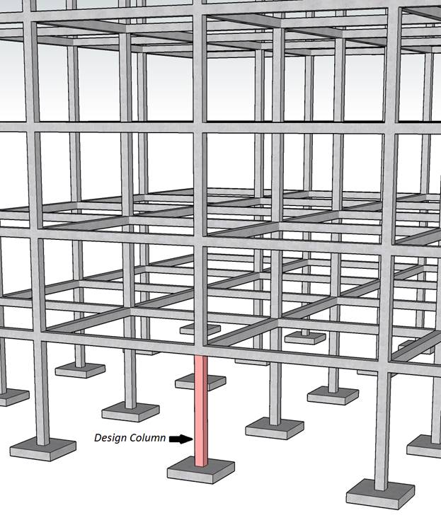
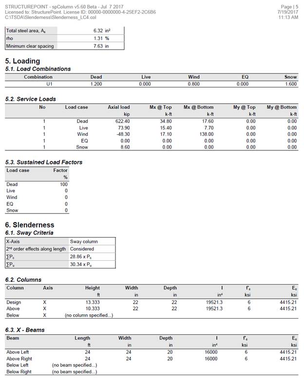
Evaluate slenderness effect for columns in a sway frame multistory reinforced concrete building by designing the first story exterior column. The clear height of the first story is 13 ft-4 in., and is 10 ft-4in. for all of the other stories. Lateral load effects on the building are governed by wind forces. Compare the calculated results with the values presented in the Reference and with exact values from spColumn engineering software program from StructurePoint.
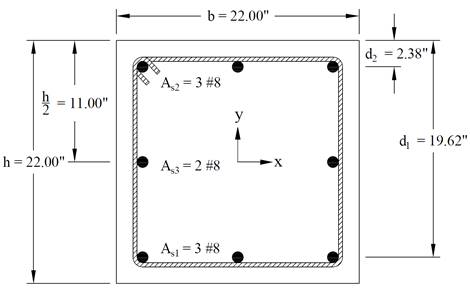
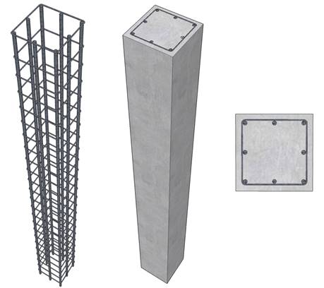
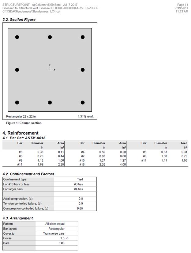
Figure 1 – Reinforced Concrete Column Cross-Section
Contents
1. Factored Axial Loads and Bending Moments
1.2. Load Combinations – Factored Loads
2. Slenderness Effects and Sway or Nonsway Frame Designation
3. Determine Slenderness Effects
4. Moment Magnification at Ends of Compression Member
5. Moment Magnification along Length of Compression Member
6.1. c, a, and strains in the reinforcement
6.2. Forces in the concrete and steel
7. Column Interaction Diagram - spColumn Software
8. Summary and Comparison of Design Results
Code
Building Code Requirements for Structural Concrete (ACI 318-14) and Commentary (ACI 318R-14)
Reference
Notes on ACI 318-11 Building Code Requirements for Structural Concrete, Twelfth Edition, 2013 Portland Cement Association, Example 11-2
Design Data
fc’ = 6,000 psi for columns in the bottom two stories
= 4,000 psi elsewhere
fy = 60,000 psi
Slab thickness = 7 in.
Exterior Columns = 22 in. x 22 in.
Interior Columns = 24 in. x 24 in.
Beams = 24 in. x 20 in. x 24 ft
Superimposed dead load = 30 psf
Roof live load = 30 psf
Floor live load = 50 psf
Wind loads computed according to ASCE 7-10
Total building loads in the first story from structural analysis:
D = 17,895 kip
L = 1,991 kip
Lr = 270 kip
W = 0 kip, wind loads in the story cause compression in some columns and tension in others and thus would cancel out.
|
Table 1 - Exterior column service loads |
|||
|
Load Case |
Axial Load, |
Bending Moment, ft-kip |
|
|
Top |
Bottom |
||
|
Dead, D |
622.4 |
34.8 |
17.6 |
|
Live, L |
73.9 |
15.4 |
7.7 |
|
Roof Live, Lr |
8.6 |
0.0 |
0.0 |
|
Wind, W (N-S) |
-48.3 |
17.1 |
138.0 |
|
Wind, W (S-N) |
48.3 |
-17.1 |
-138.0 |
|
Table 2 - Exterior column factored loads |
|||||||||
|
ASCE 7-10 |
No. |
Load Combination |
Axial Load, |
Bending Moment,
|
MTop,ns |
MBottom,ns |
MTop,s |
MBottom,s |
|
|
Top |
Bottom |
||||||||
|
2.3.2-1 |
1 |
1.4D |
871.4 |
48.7 |
24.6 |
48.7 |
24.6 |
--- |
--- |
|
2.3.2-2 |
2 |
1.2D + 1.6L + 0.5Lr |
869.4 |
66.4 |
33.4 |
66.4 |
33.4 |
--- |
--- |
|
2.3.2-3 |
3 |
1.2D + 0.5L + 1.6 Lr |
797.6 |
49.5 |
25.0 |
49.5 |
25.0 |
--- |
--- |
|
4 |
1.2D + 1.6Lr + 0.8W |
722.0 |
55.4 |
131.5 |
41.8 |
21.1 |
13.7 |
110.4 |
|
|
5 |
1.2D + 1.6Lr - 0.8W |
799.3 |
28.1 |
-89.3 |
41.8 |
21.1 |
-13.7 |
-110.4 |
|
|
2.3.2-4 |
6 |
1.2D + 0.5L + 0.5Lr + 1.6W |
710.9 |
76.8 |
245.8 |
49.5 |
25.0 |
27.4 |
220.8 |
|
7 |
1.2D + 0.5L + 0.5Lr - 1.6W |
865.4 |
22.1 |
-195.8 |
49.5 |
25.0 |
-27.4 |
-220.8 |
|
|
2.3.2-6 |
8 |
0.9D + 1.6W |
482.9 |
58.7 |
236.6 |
31.3 |
15.8 |
27.4 |
220.8 |
|
9 |
0.9D - 1.6W |
637.4 |
4.0 |
-205.0 |
31.3 |
15.8 |
-27.4 |
-220.8 |
|
Columns and stories in structures are considered as non-sway frames if the increase in column end moments due to second-order effects does not exceed 5% of the first-order end moments, or the stability index for the story (Q) does not exceed 0.05. ACI 318-14 (6.6.4.3)
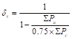
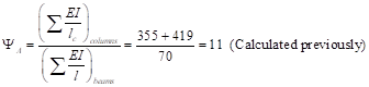
∑Pu is the total vertical load in the first story corresponding to the lateral loading case for which ∑Pu is greatest (without the wind loads, which would cause compression in some columns and tension in others and thus would cancel out). ACI 318-14 (6.6.4.4.1 and R6.6.4.3)
Vus is the factored horizontal story shear in the first story corresponding to the wind loads, and Δo is the first-order relative deflection between the top and bottom of the first story due to Vu. ACI 318-14 (6.6.4.4.1 and R6.6.4.3)
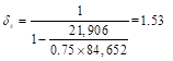
From Table 2, load combinations (2.3.2-4 No. 5 and 6) provide the greatest value of ∑Pu.
![]() ASCE 7-10 (2.3.2-4)
ASCE 7-10 (2.3.2-4)
![]() ASCE 7-10 (2.3.2-6)
ASCE 7-10 (2.3.2-6)
![]()
![]() ACI 318-14 (Eq. 6.6.4.4.1)
ACI 318-14 (Eq. 6.6.4.4.1)
Thus, the frame at the first story level is considered sway.
![]() ACI 318-14 (Table 6.6.3.1.1(a))
ACI 318-14 (Table 6.6.3.1.1(a))
![]() ACI 318-14 (19.2.2.1.b)
ACI 318-14 (19.2.2.1.b)
For the column below level 2:
![]()
For the column above level 2:
![]()
For beams framing into the columns:
![]()
Where:
![]() ACI 318-14 (19.2.2.1.b)
ACI 318-14 (19.2.2.1.b)
![]() ACI 318-14 (Table 6.6.3.1.1(a))
ACI 318-14 (Table 6.6.3.1.1(a))
 ACI 318-14 (Figure R6.2.5)
![]() (Column
essentially fixed at base) ACI 318-14 (Figure R6.2.5)
(Column
essentially fixed at base) ACI 318-14 (Figure R6.2.5)
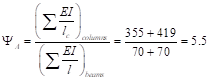
Using Figure R6.2.5 from ACI 318-14 à k = 1.9 as shown in the figure below for the exterior columns with one beam framing into them in the directions of analysis.
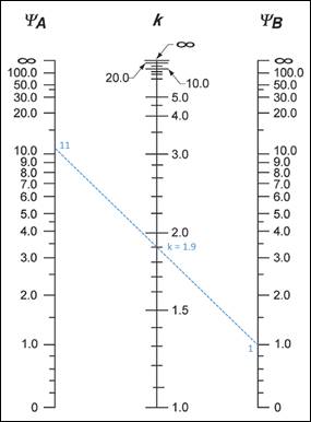
Figure 2 – Effective Length Factor (k) Calculations for Exterior Columns with One Beam Framing into them in the Direction of Analysis (Sway Frame)
![]() ACI 318-14 (6.2.5a)
ACI 318-14 (6.2.5a)
Where:
![]() ACI 318-14 (6.2.5.1)
ACI 318-14 (6.2.5.1)
![]()
A detailed calculation for load combination 4 (gravity plus wind) is shown below to illustrate the procedure. Table 3 summarizes the magnified moment computations for the exterior columns.
![]() ACI 318-14 (6.6.4.6.1b)
ACI 318-14 (6.6.4.6.1b)
Where:
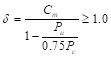
 ACI 318-14 (6.6.4.6.2)
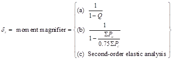
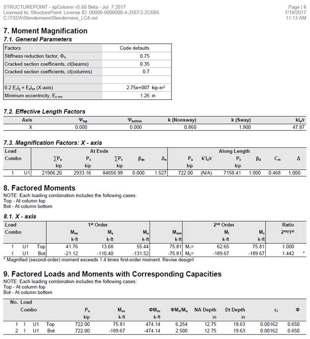
ACI 318-14 (6.6.4.6.2(b)) will be used for comparison purposes with results obtained from spColumn model. However, (a) and (c) can also be used to calculate the moment magnifier.
∑Pu is the summation of all the factored vertical loads in the first story, and ∑Pc is the summation of the critical buckling load for all sway-resisting columns in the first story.
![]() ACI 318-14 (6.6.4.4.2)
ACI 318-14 (6.6.4.4.2)
Where:
 ACI 318-14 (6.6.4.4.4)
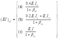
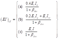
There are three options for calculating the effective flexural stiffness of slender concrete columns (EI)eff. The second equation provides accurate representation of the reinforcement in the section and will be used in this example and is also used by the solver in spColumn. Further comparison of the available options is provided in “Effective Flexural Stiffness for Critical Buckling Load of Concrete Columns” technical note.
![]() ACI 318-14 (Table 6.6.3.1.1(a))
ACI 318-14 (Table 6.6.3.1.1(a))
![]() ACI 318-14 (19.2.2.1.a)
ACI 318-14 (19.2.2.1.a)
βds is the ratio of maximum factored sustained shear within a story to the maximum factored shear in that story associated with the same load combination. The maximum factored sustained shear in this example is equal to zero leading to βds = 0. ACI 318-14 (6.6.3.1.1)
For exterior columns with one beam framing into them in the direction of analysis (12 columns):
With 8-#8 reinforcement equally distributed on all sides and 22 in. x 22 in. column section à Ise = 352.6 in.4.
![]() ACI 318-14 (6.6.4.4.4(b))
ACI 318-14 (6.6.4.4.4(b))
![]()
k = 1.9 (calculated previously).
![]()
For exterior columns with two beams framing into them in the direction of analysis (4 columns):
 ACI 318-14 (Figure R6.2.5)
![]() (Column
essentially fixed at base) ACI 318-14 (Figure R6.2.5)
(Column
essentially fixed at base) ACI 318-14 (Figure R6.2.5)
Using Figure R6.2.5 from ACI 318-14 à k = 1.71 as shown in the figure below for the exterior columns with two beams framing into them in the directions of analysis.
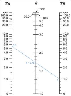
Figure 3 – Effective Length Factor (k) Calculations for Exterior Columns with Two Beams Framing into them in the Direction of Analysis
![]()
For interior columns (8 columns):
![]() ACI 318-14 (Table 6.6.3.1.1(a))
ACI 318-14 (Table 6.6.3.1.1(a))
![]() ACI 318-14 (19.2.2.1.a)
ACI 318-14 (19.2.2.1.a)
For the column below level 2:
![]()
For the column above level 2:
![]()
For beams framing into the columns:
![]()
Where:
![]() ACI 318-14 (19.2.2.1.a)
ACI 318-14 (19.2.2.1.a)
![]() ACI 318-14 (Table 6.6.3.1.1(a))
ACI 318-14 (Table 6.6.3.1.1(a))
 ACI 318-14 (Figure R6.2.5)
![]() (Column
essentially fixed at base) ACI 318-14 (Figure R6.2.5)
(Column
essentially fixed at base) ACI 318-14 (Figure R6.2.5)
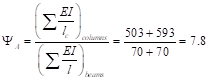
Using Figure R6.2.5 from ACI 318-14 à k = 1.81 as shown in the figure below for the interior columns.
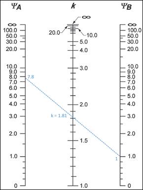
Figure 4 – Effective Length Factor (k) Calculations for Interior Columns
With 8-#8 reinforcement equally distributed on all sides and 24 in. x 24 in. column section à Ise = 439.1 in.4.
![]() ACI 318-14 (6.6.4.4.4(b))
ACI 318-14 (6.6.4.4.4(b))
![]()
![]()
![]()
![]()
For load combination 4:
![]() ASCE 7-10 (2.3.2-3)
ASCE 7-10 (2.3.2-3)
 ACI 318-14 (6.6.4.6.2(b))
![]()
![]() ACI 318-14 (6.6.4.6.1)
ACI 318-14 (6.6.4.6.1)
![]()
![]() ACI 318-14 (6.6.4.6.1)
ACI 318-14 (6.6.4.6.1)
![]()
![]()
Pu = 722.0 kip
A summary of the moment magnification factors and magnified moments for the exterior column for all load combinations using both equation options ACI 318-14 (6.6.4.4.4(a)) and (6.6.4.4.4(b)) to calculate (EI)eff is provided in the table below for illustration and comparison purposes. Note: The designation of M1 and M2 is made based on the second-order (magnified) moments and not based on the first-order (unmagnified) moments.
Table 3 - Factored Axial loads and Magnified Moments for Exterior Column |
||||||||
|
No. |
Load Combination |
Axial Load, kip |
Using ACI 6.6.4.4.4(a) |
Using ACI 6.6.4.4.4(b) |
||||
|
δs |
M1, ft-kip |
M2, ft-kip |
δs |
M1, ft-kip |
M2, ft-kip |
|||
|
1 |
1.4D |
871.4 |
--- |
24.6 |
48.7 |
--- |
24.6 |
48.7 |
|
2 |
1.2D + 1.6L + 0.5Lr |
869.4 |
--- |
33.4 |
66.4 |
--- |
33.4 |
66.4 |
|
3 |
1.2D + 0.5L + 1.6 Lr |
797.6 |
--- |
25.0 |
49.5 |
--- |
25.0 |
49.5 |
|
4 |
1.2D + 1.6Lr + 0.8W |
722.0 |
1.37 |
60.6 |
172.3 |
1.53 |
62.7 |
189.7 |
|
5 |
1.2D + 1.6Lr - 0.8W |
799.3 |
1.37 |
23.0 |
-130.1 |
1.53 |
20.9 |
-147.5 |
|
6 |
1.2D + 0.5L + 0.5Lr + 1.6W |
710.9 |
1.39 |
87.5 |
330.9 |
1.55 |
92.0 |
367.9 |
|
7 |
1.2D + 0.5L + 0.5Lr - 1.6W |
865.4 |
1.39 |
11.5 |
-280.9 |
1.55 |
7.0 |
-317.9 |
|
8 |
0.9D + 1.6W |
482.9 |
1.25 |
65.5 |
291.2 |
1.34 |
68.0 |
311.6 |
|
9 |
0.9D - 1.6W |
637.4 |
1.25 |
-2.9 |
-259.6 |
1.34 |
-5.4 |
-280.0 |
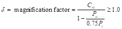
In sway frames, second-order effects shall be considered along the length of columns. It shall be permitted to account for these effects using ACI 318-14 (6.6.4.5) (Nonsway frame procedure), where Cm is calculated using M1 and M2 from ACI 318-14 (6.6.4.6.1) as follows: ACI 318-14 (6.6.4.6.4)
![]() ACI 318-14 (6.6.4.5.1)
ACI 318-14 (6.6.4.5.1)
Where:
M2 = the second-order factored moment.
 ACI 318-14 (6.6.4.5.2)
![]() ACI 318-14 (6.6.4.4.2)
ACI 318-14 (6.6.4.4.2)
Where:
 ACI 318-14 (6.6.4.4.4)
There are three options for calculating the effective flexural stiffness of slender concrete columns (EI)eff. The second equation provides accurate representation of the reinforcement in the section and will be used in this example and is also used by the solver in spColumn. Further comparison of the available options is provided in “Effective Flexural Stiffness for Critical Buckling Load of Concrete Columns” technical note.
![]() ACI 318-14 (Table 6.6.3.1.1(a))
ACI 318-14 (Table 6.6.3.1.1(a))
![]() ACI 318-14 (19.2.2.1.a)
ACI 318-14 (19.2.2.1.a)
βdns is the ratio of maximum factored sustained axial load to maximum factored axial load associated with the same load combination. ACI 318-14 (6.6.4.4.4)
For load combination 4:
![]()
![]()
![]()
 ACI 318-14 (Figure R6.2.5)
![]() (Column
essentially fixed at base) ACI 318-14 (Figure R6.2.5)
(Column
essentially fixed at base) ACI 318-14 (Figure R6.2.5)
Using Figure R6.2.5(a) from ACI 318-14 à k = 0.86 as shown in the figure below for the exterior column.
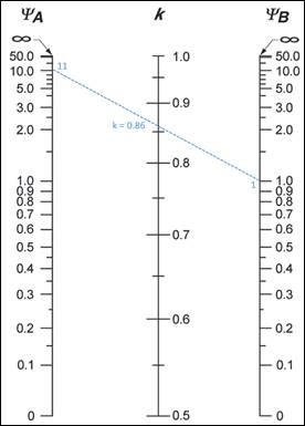
Figure 5 – Effective Length Factor (k) Calculations for Exterior Column (Nonsway)
With 8-#8 reinforcement equally distributed on all sides and 22 in. x 22 in. column section à Ise = 352.6 in.4.
![]() ACI 318-14 (6.6.4.4.4(b))
ACI 318-14 (6.6.4.4.4(b))
![]()
![]()
For load combination 4:
![]() ASCE 7-10 (2.3.2-3)
ASCE 7-10 (2.3.2-3)
![]() ACI 318-14 (6.6.4.5.3a)
ACI 318-14 (6.6.4.5.3a)
![]() ACI 318-14 (6.6.4.6.4)
ACI 318-14 (6.6.4.6.4)
![]() ACI 318-14 (6.6.4.6.4)
ACI 318-14 (6.6.4.6.4)
Since the column is bent in double curvature, M1/M2 is positive. ACI 318-14 (6.6.4.5.3)
![]()
 ACI 318-14 (6.6.4.5.2)
![]() ACI 318-14 (6.6.4.5.4)
ACI 318-14 (6.6.4.5.4)
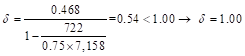
Where Pu = 722 kip, and h = the section dimension in the direction being considered = 22 in.
![]()
![]() ACI 318-14 (6.6.4.5.4)
ACI 318-14 (6.6.4.5.4)
![]() ACI 318-14 (6.6.4.5.1)
ACI 318-14 (6.6.4.5.1)
![]()
![]() ACI 318-14 (6.6.4.5.4)
ACI 318-14 (6.6.4.5.4)
![]() ACI 318-14 (6.6.4.5.1)
ACI 318-14 (6.6.4.5.1)
![]()
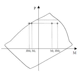
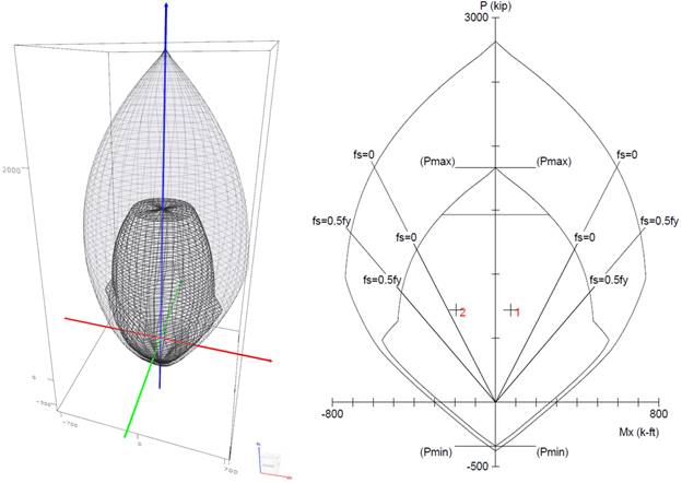
Figure 6 – Column Interaction Diagram for Unsymmetrical Section
A summary of the moment magnification factors and magnified moments for the exterior column for all load combinations using both equation options ACI 318-14 (6.6.4.4.4(a)) and (6.6.4.4.4(b)) to calculate (EI)eff is provided in the table below for illustration and comparison purposes.
|
Table 4 - Factored Axial loads and Magnified Moments along Exterior Column Length |
||||||||
|
No. |
Load Combination |
Axial Load, kip |
Using ACI 6.6.4.4.4(a) |
Using ACI 6.6.4.4.4(b) |
||||
|
δ |
Mc1, ft-kip |
Mc2, ft-kip |
δ |
Mc1, ft-kip |
Mc2, ft-kip |
|||
|
1 |
1.4D |
871.4 |
1.00 |
91.5 |
91.5 |
1.00 |
91.5 |
91.5 |
|
2 |
1.2D + 1.6L + 0.5Lr |
869.4 |
1.00 |
91.3 |
91.3 |
1.00 |
91.3 |
91.3 |
|
3 |
1.2D + 0.5L + 1.6 Lr |
797.6 |
1.00 |
83.7 |
83.7 |
1.00 |
83.7 |
83.7 |
|
4 |
1.2D + 1.6Lr + 0.8W |
722.0 |
1.00 |
75.8 |
172.3 |
1.00 |
75.8 |
189.7 |
|
5 |
1.2D + 1.6Lr - 0.8W |
799.3 |
1.00 |
83.9 |
-130.1 |
1.00 |
83.9 |
-147.5 |
|
6 |
1.2D + 0.5L + 0.5Lr + 1.6W |
710.9 |
1.00 |
87.5 |
330.9 |
1.00 |
92.0 |
367.9 |
|
7 |
1.2D + 0.5L + 0.5Lr - 1.6W |
865.4 |
1.00 |
90.9 |
-280.9 |
1.00 |
90.9 |
-317.9 |
|
8 |
0.9D + 1.6W |
482.9 |
1.00 |
65.5 |
291.2 |
1.00 |
68.0 |
311.6 |
|
9 |
0.9D - 1.6W |
637.4 |
1.00 |
66.9 |
-259.6 |
1.00 |
66.9 |
-280.0 |
For column design ACI 318 requires the second-order moment to first-order moment ratios should not exceed 1.40. If this value is exceeded, the column design needs to be revised. ACI 318-14 (6.2.6)
|
Table 5 - Second-Order Moment to First-Order Moment Ratios |
|||||
|
No. |
Load Combination |
Using ACI 6.6.4.4.4(a) |
Using ACI 6.6.4.4.4(b) |
||
|
Mc1/M1(1st) |
Mc2/M2(1st) |
Mc1/M1(1st) |
Mc2/M2(1st) |
||
|
1 |
1.4D |
1.00* |
1.00* |
1.00* |
1.00* |
|
2 |
1.2D + 1.6L + 0.5Lr |
1.00* |
1.00* |
1.00* |
1.00* |
|
3 |
1.2D + 0.5L + 1.6 Lr |
1.00* |
1.00* |
1.00* |
1.00* |
|
4 |
1.2D + 1.6Lr + 0.8W |
1.00* |
1.31 |
1.00* |
1.40 < 1.44 |
|
5 |
1.2D + 1.6Lr - 0.8W |
1.00* |
1.40 < 1.46 |
1.00* |
1.40 < 1.65 |
|
6 |
1.2D + 0.5L + 0.5Lr + 1.6W |
1.14 |
1.35 |
1.20 |
1.40 < 1.50 |
|
7 |
1.2D + 0.5L + 0.5Lr - 1.6W |
1.00* |
1.40 < 1.43 |
1.00* |
1.40 < 1.62 |
|
8 |
0.9D + 1.6W |
1.12 |
1.23 |
1.16 |
1.32 |
|
9 |
0.9D - 1.6W |
1.00* |
1.27 |
1.00* |
1.37 |
|
* Cutoff value of Mmin is applied to M1(1st) and M2(1st) in order to avoid unduly large ratios in cases where M1(1st) and M2(1st) moments are smaller than Mmin. |
|||||
Based on the factored axial loads and magnified moments considering slenderness effects, the capacity of the assumed column section (22 in. x 22 in. with 8-#8 bars distributed all sides equal) will be checked and confirmed to finalize the design. A column interaction diagram will be generated using strain compatibility analysis, the detailed procedure to develop column interaction diagram can be found in “Interaction Diagram – Tied Reinforced Concrete Column” example.
The axial compression capacity ϕPn for all load combinations will be set equals to Pu, then the moment capacity ϕMn associated to ϕPn will be compared with the magnified applied moment Mu. The design check for load combination #4 is shown below for illustration. The rest of the checks for the other load combinations are shown in the following Table.
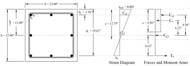
Figure 7 – Strains, Forces, and Moment Arms (Load Combination 4)
The following procedure is used to determine the nominal moment capacity by setting the design axial load capacity, ϕPn, equal to the applied axial load, Pu and iterating on the location of the neutral axis.
![]()
Where c is the distance from the fiber of maximum compressive strain to the neutral axis.
ACI 318-14 (22.2.2.4.2)
![]() ACI 318-14 (22.2.2.4.1)
ACI 318-14 (22.2.2.4.1)
Where:
![]() ACI 318-14 (Table 22.2.2.4.3)
ACI 318-14 (Table 22.2.2.4.3)
![]() ACI
318-14 (22.2.2.1)
ACI
318-14 (22.2.2.1)
![]()
![]()
![]()
![]() ACI
318-14 (Table 21.2.2)
ACI
318-14 (Table 21.2.2)
![]()
![]()
![]() ACI 318-14 (22.2.2.4.1)
ACI 318-14 (22.2.2.4.1)
![]()
![]()
![]()
![]()
![]()
![]()
The area of the reinforcement in this layer has been included in the area (ab) used to compute Cc. As a result, it is necessary to subtract 0.85fc’ from fs’ before computing Cs:
![]()
![]()
![]()
![]()
The assumption that c = 12.75 in. is correct
![]()
![]()
![]()
|
Table 6 – Exterior Column Axial and Moment Capacities |
|||||||
|
No. |
Pu, kip |
Mu = M2(2nd), ft-kip |
c, in. |
εt = εs |
φ |
φPn, kip |
φMn, kip.ft |
|
1 |
871.4 |
91.5 |
14.85 |
0.00096 |
0.65 |
871.4 |
459.4 |
|
2 |
869.4 |
91.3 |
14.85 |
0.00097 |
0.65 |
869.4 |
459.7 |
|
3 |
797.6 |
83.7 |
13.75 |
0.00128 |
0.65 |
797.6 |
468.2 |
|
4 |
722.0 |
189.7 |
12.75 |
0.00162 |
0.65 |
722.0 |
474.1 |
|
5 |
799.3 |
-147.5 |
13.78 |
0.00127 |
0.65 |
799.3 |
468.0 |
|
6 |
710.9 |
367.9 |
12.61 |
0.00167 |
0.65 |
710.9 |
474.8 |
|
7 |
865.4 |
-317.9 |
14.76 |
0.00099 |
0.65 |
865.4 |
460.2 |
|
8 |
482.9 |
311.6 |
7.36 |
0.005 |
0.9 |
482.9 |
557.2 |
|
9 |
637.4 |
-280.0 |
11.68 |
0.00204 |
0.65 |
637.4 |
478.8 |
Therefore, since ϕMn > Mu for all ϕPn = Pu, use 22 x 22 in. column with 8-#8 bars.
spColumn program performs the analysis of the reinforced concrete section conforming to the provisions of the Strength Design Method and Unified Design Provisions with all conditions of strength satisfying the applicable conditions of equilibrium and strain compatibility and includes slenderness effects using moment magnification method for sway and nonsway frames. For this column section, we ran in investigation mode with control points using the 318-14. In lieu of using program shortcuts, spSection (Figure 8) was used to place the reinforcement and define the cover to illustrate handling of irregular shapes and unusual bar arrangement.
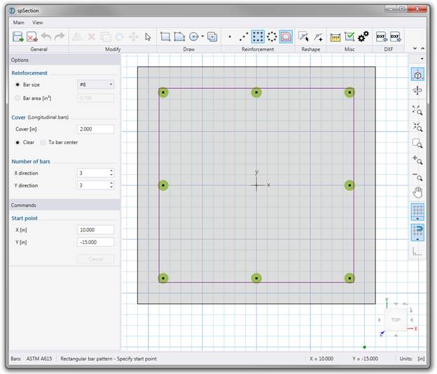
Figure 8 – spColumn Model Editor (spSection)
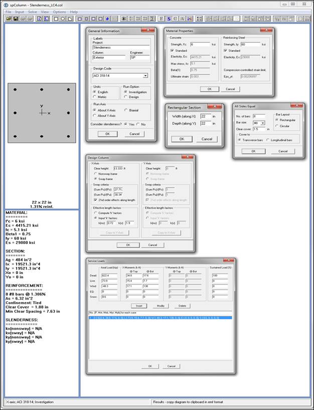
Figure 9 –spColumn Model Input Wizard Windows
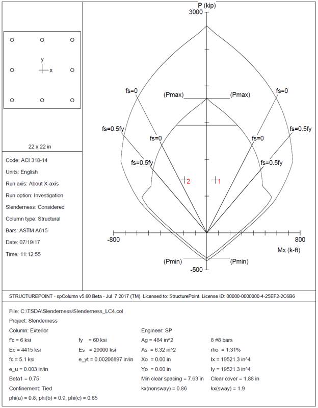
Figure 10 – Column Section Interaction Diagram about the X-Axis – Design Check for Load Combination 4 (spColumn)
|
Table 7 - Factored Axial loads and Magnified Moments at Column Ends Comparison |
||||||||||||
|
No. |
Pu, kip |
δs |
M1(2nd), ft-kip |
M2(2nd), ft-kip |
||||||||
|
Hand |
Reference |
spColumn |
Hand |
Reference |
spColumn |
Hand |
Reference |
spColumn |
Hand |
Reference* |
spColumn |
|
|
1 |
871.4 |
871.4 |
871.4 |
N/A |
N/A |
N/A |
24.6 |
24.6 |
24.6 |
48.7 |
48.7 |
48.7 |
|
2 |
869.4 |
869.4 |
869.4 |
N/A |
N/A |
N/A |
33.4 |
33.4 |
33.4 |
66.4 |
66.4 |
66.4 |
|
3 |
797.6 |
797.6 |
797.6 |
N/A |
N/A |
N/A |
25.0 |
25.0 |
25.0 |
49.5 |
49.5 |
49.5 |
|
4 |
722.0 |
722.0 |
722.0 |
1.53 |
1.38 |
1.53 |
62.7 |
60.6 |
62.7 |
189.7 |
173.5 |
189.7 |
|
5 |
799.3 |
799.3 |
799.3 |
1.53 |
1.38 |
1.53 |
20.9 |
23.0 |
20.9 |
-147.5 |
-131.3 |
-147.4 |
|
6 |
710.9 |
710.9 |
7110.9 |
1.55 |
1.39 |
1.55 |
92.0 |
87.5 |
92.0 |
367.9 |
331.9 |
367.8 |
|
7 |
865.4 |
865.4 |
865.4 |
1.55 |
1.39 |
1.55 |
7.0 |
11.5 |
7.0 |
-317.9 |
-281.9 |
-317.9 |
|
8 |
482.9 |
482.9 |
482.9 |
1.34 |
1.25 |
1.34 |
68.0 |
65.5 |
68.0 |
311.6 |
292.0 |
311.7 |
|
9 |
637.4 |
637.4 |
637.4 |
1.34 |
1.25 |
1.34 |
-5.4 |
-2.9 |
-5.3 |
-280.0 |
-260.3 |
280.0 |
|
Table 8 - Magnified Moments along Column Length to First-Order Moment Ratios Comparison |
|||||||||||||||
|
No. |
δ |
Mc1, ft-kip |
Mc2, ft-kip |
Mc1/M1(1st) |
Mc2/M2(1st) |
||||||||||
|
Hand |
Reference* |
spColumn |
Hand |
Reference* |
spColumn |
Hand |
Reference* |
spColumn |
Hand |
Reference* |
spColumn |
Hand |
Reference* |
spColumn |
|
|
1 |
1.00 |
--- |
1.00 |
91.5 |
--- |
91.5 |
91.5 |
--- |
91.5 |
1.00 |
--- |
1.00 |
1.00 |
--- |
1.00 |
|
2 |
1.00 |
--- |
1.00 |
91.3 |
--- |
91.3 |
91.3 |
--- |
91.3 |
1.00 |
--- |
1.00 |
1.00 |
--- |
1.00 |
|
3 |
1.00 |
--- |
1.00 |
83.7 |
--- |
83.7 |
83.7 |
--- |
83.7 |
1.00 |
--- |
1.00 |
1.00 |
--- |
1.00 |
|
4 |
1.00 |
--- |
1.00 |
75.8 |
--- |
75.8 |
189.7 |
--- |
189.7 |
1.00 |
--- |
1.00 |
1.44 |
--- |
1.44 |
|
5 |
1.00 |
--- |
1.00 |
83.9 |
--- |
83.9 |
-147.5 |
--- |
-147.4 |
1.00 |
--- |
1.00 |
1.65 |
--- |
1.65 |
|
6 |
1.00 |
--- |
1.00 |
92.0 |
--- |
92.0 |
367.9 |
--- |
367.8 |
1.20 |
--- |
1.20 |
1.50 |
--- |
1.50 |
|
7 |
1.00 |
--- |
1.00 |
90.9 |
--- |
90.9 |
-317.9 |
--- |
-317.9 |
1.00 |
--- |
1.00 |
1.62 |
--- |
1.62 |
|
8 |
1.00 |
--- |
1.00 |
68.0 |
--- |
68.0 |
311.6 |
--- |
311.7 |
1.16 |
--- |
1.16 |
1.32 |
--- |
1.32 |
|
9 |
1.00 |
--- |
1.00 |
-66.9 |
--- |
-66.9 |
-280.0 |
--- |
280.0 |
1.00 |
--- |
1.00 |
1.37 |
--- |
1.37 |
|
* Moment magnification along the length of the column is not covered by the reference |
|||||||||||||||
|
Table 9 - Design Parameters Comparison |
|||||||||||||||
|
No. |
c, in. |
εt = εs |
φ |
φPn, kip |
φMn, kip.ft |
||||||||||
|
Hand |
Reference* |
spColumn |
Hand |
Reference* |
spColumn |
Hand |
Reference* |
spColumn |
Hand |
Reference* |
spColumn |
Hand |
Reference* |
spColumn |
|
|
1 |
14.85 |
14.85 |
14.85 |
0.00096 |
0.00096 |
0.00096 |
0.65 |
0.65 |
0.65 |
871.4 |
871.4 |
871.4 |
459.4 |
459.4 |
459.4 |
|
2 |
14.85 |
14.82 |
14.85 |
0.00097 |
0.00097 |
0.00097 |
0.65 |
0.65 |
0.65 |
869.4 |
869.4 |
869.4 |
459.7 |
459.7 |
459.7 |
|
3 |
13.75 |
13.75 |
13.75 |
0.00128 |
0.00128 |
0.00128 |
0.65 |
0.65 |
0.65 |
797.6 |
797.6 |
797.6 |
468.2 |
468.2 |
468.2 |
|
4 |
12.75 |
12.75 |
12.75 |
0.00162 |
0.00162 |
0.00162 |
0.65 |
0.65 |
0.65 |
722.0 |
722.0 |
722.0 |
474.1 |
474.1 |
474.1 |
|
5 |
13.78 |
13.78 |
13.78 |
0.00127 |
0.00127 |
0.00127 |
0.65 |
0.65 |
0.65 |
799.3 |
799.3 |
799.3 |
468.0 |
468.0 |
468.0 |
|
6 |
12.61 |
12.61 |
12.61 |
0.00167 |
0.00167 |
0.00167 |
0.65 |
0.65 |
0.65 |
710.9 |
710.9 |
7110.9 |
474.8 |
474.8 |
474.8 |
|
7 |
14.76 |
14.76 |
14.76 |
0.00099 |
0.00099 |
0.00099 |
0.65 |
0.65 |
0.65 |
865.4 |
865.4 |
865.4 |
460.2 |
460.2 |
460.2 |
|
8 |
7.36 |
7.36 |
7.36 |
0.00500 |
0.00500 |
0.00500 |
0.90 |
0.90 |
0.90 |
482.9 |
482.9 |
482.9 |
557.2 |
557.2 |
557.2 |
|
9 |
11.68 |
11.68 |
11.68 |
0.00204 |
0.00204 |
0.00204 |
0.65 |
0.65 |
0.65 |
637.4 |
637.4 |
637.4 |
478.8 |
478.8 |
478.8 |
|
* Notes on ACI 318-11 Building Code Requirements for Structural Concrete, Twelfth Edition, 2013 Portland Cement Association, Example 11-2 |
|||||||||||||||
In all of the hand calculations and the reference used illustrated above, the results are in precise agreement with the automated exact results obtained from the spColumn program.
The analysis of the reinforced concrete section performed by spColumn conforms to the provisions of the Strength Design Method and Unified Design Provisions with all conditions of strength satisfying the applicable conditions of equilibrium and strain compatibility and includes slenderness effects using moment magnification method for sway and nonsway frames.
ACI 318 provides multiple options for calculating values of k, (EI)eff , δs, and δ leading to variability in the determination of the adequacy of a column section. Engineers must exercise judgment in selecting suitable options to match their design condition as is the case in the reference where the author conservatively made assumptions to simplify and speed the calculation effort. The spColumn program utilizes the exact methods whenever possible and allows user to override the calculated values with direct input based on their engineering judgment wherever it is permissible.
In load combinations 4 to 7, Mu including second-order effects exceeds 1.4 Mu due to first-order effects (see Table 5). This indicates that in this building, the weight of the structure is high in proportion to its lateral stiffness leading to excessive PΔ effect (secondary moments are more than 25 percent of the primary moments). The PΔ effects will eventually introduce singularities into the solution to the equations of equilibrium, indicating physical structural instability. It was concluded in the literature that the probability of stability failure increases rapidly when the stability index Q exceeds 0.2, which is equivalent to a secondary-to-primary moment ratio of 1.25. The maximum value of the stability coefficient θ (according to ASCE/SEI 7) which is close to stability coefficient Q (according to ACI 318) is 0.25. The value 0.25 is equivalent to a secondary-to-primary moment ratio of 1.33. Hence, the upper limit of 1.4 on the secondary-to-primary moment ratio was selected by the ACI 318.
The moment magnification factor values δs calculated in this document and spColumn are different from the values calculated by the reference. ACI 318 provides three equation options to calculate the effective stiffness modulus (EI)eff as was discussed previously in this document. Equation 6.6.4.4.4(b) is more accurate than equation 6.6.4.4(a) but is more difficult to use because Ise is not known until reinforcement is chosen. The reference used equation 6.6.4.4(a) due to its simplicity while spColumn uses equation 6.6.4.4.4(b) since an iterative procedure is used to select the optimum reinforcement configuration.
As can be seen in Table 5 of this example, exploring the impact of other code permissible equation options provides the engineer added flexibility in decision making regarding design. For load combinations 4 - 7 resolving the stability concern may be viable through a frame analysis providing values for Vus and Δo to calculate magnification factor δs and may allow the proposed design to be acceptable. Creating a complete model with detailed lateral loads and load combinations to account for second order effects may not be warranted for all cases of slender column design nor is it disadvantageous to have a higher margin of safety when it comes to column slenderness and frame stability considerations.