


spFrame, is a feature-rich structural analysis program for two- and three-dimensional structures subject to static loads. Used by academic and industry professionals, it offers a quick and straightforward analysis tool.
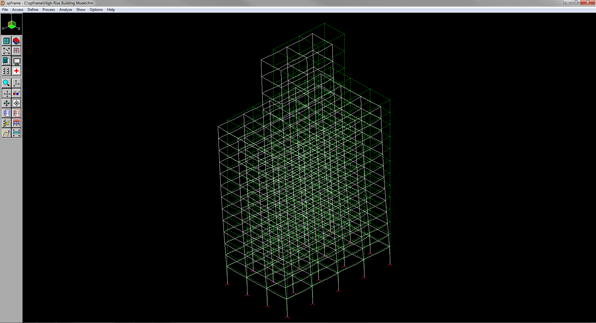
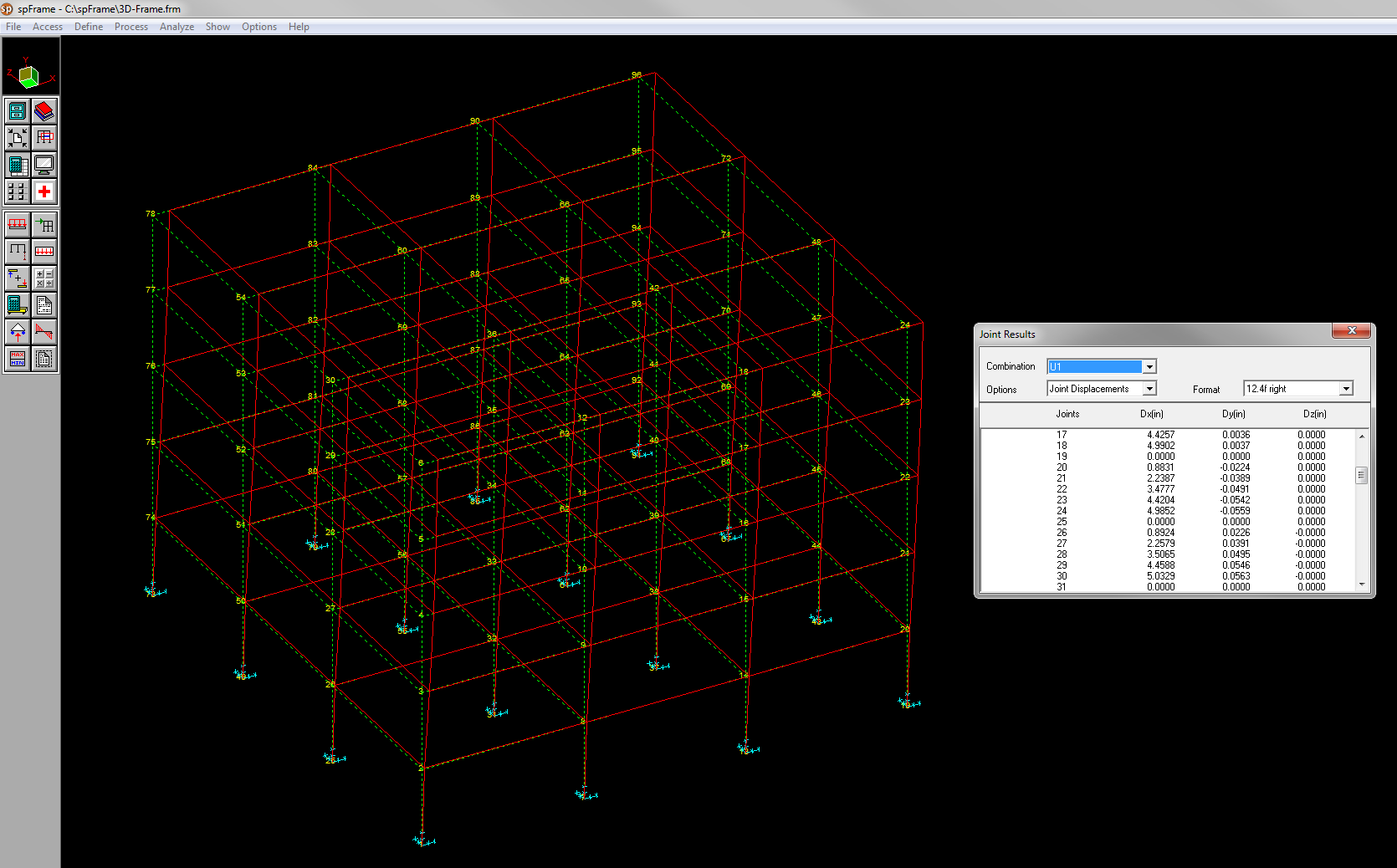
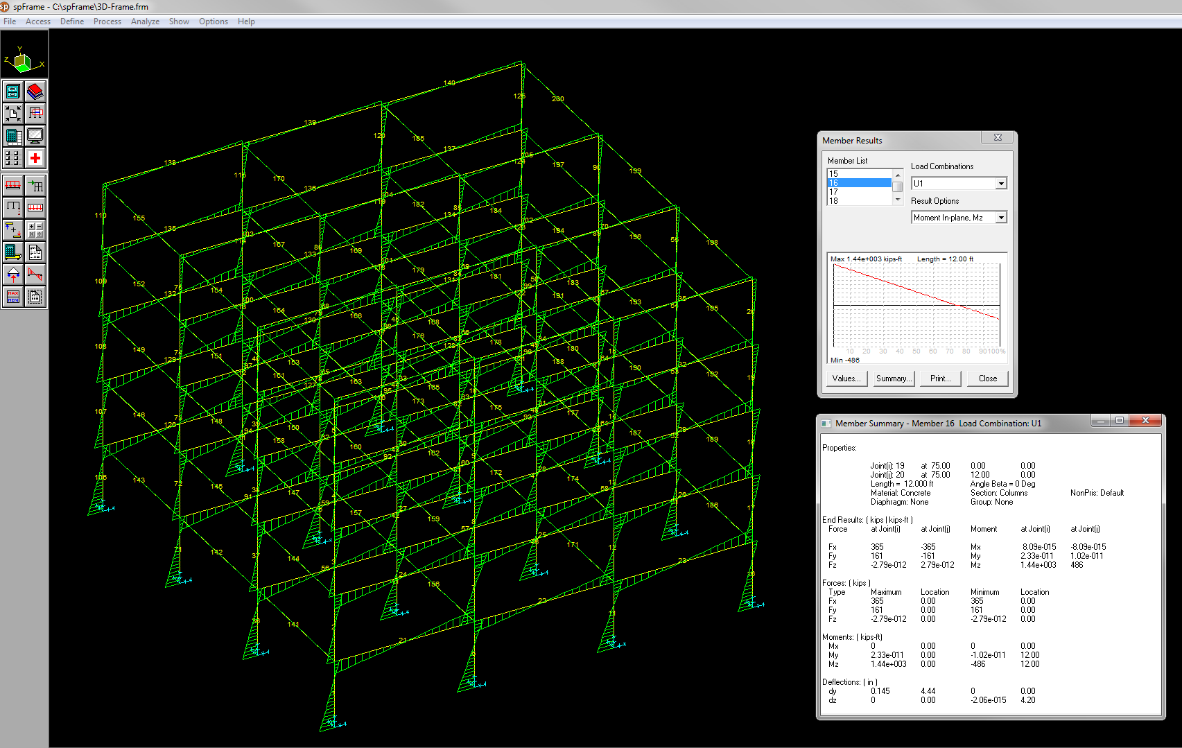
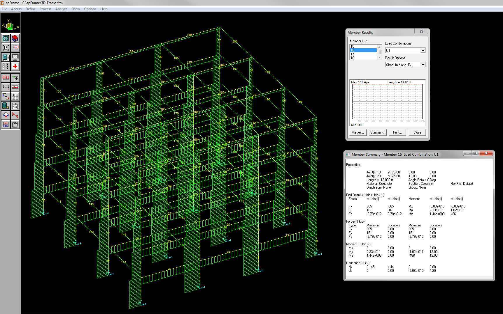
spFrame, formerly pcaFrame, has a fast and robust yet simple graphic interface that displays the modeled structure, the input loads, the deflected shape, and the resulting moment and shear diagrams. The graphic interface allows zooming, translating, rotating, and selective viewing of the graphical image.
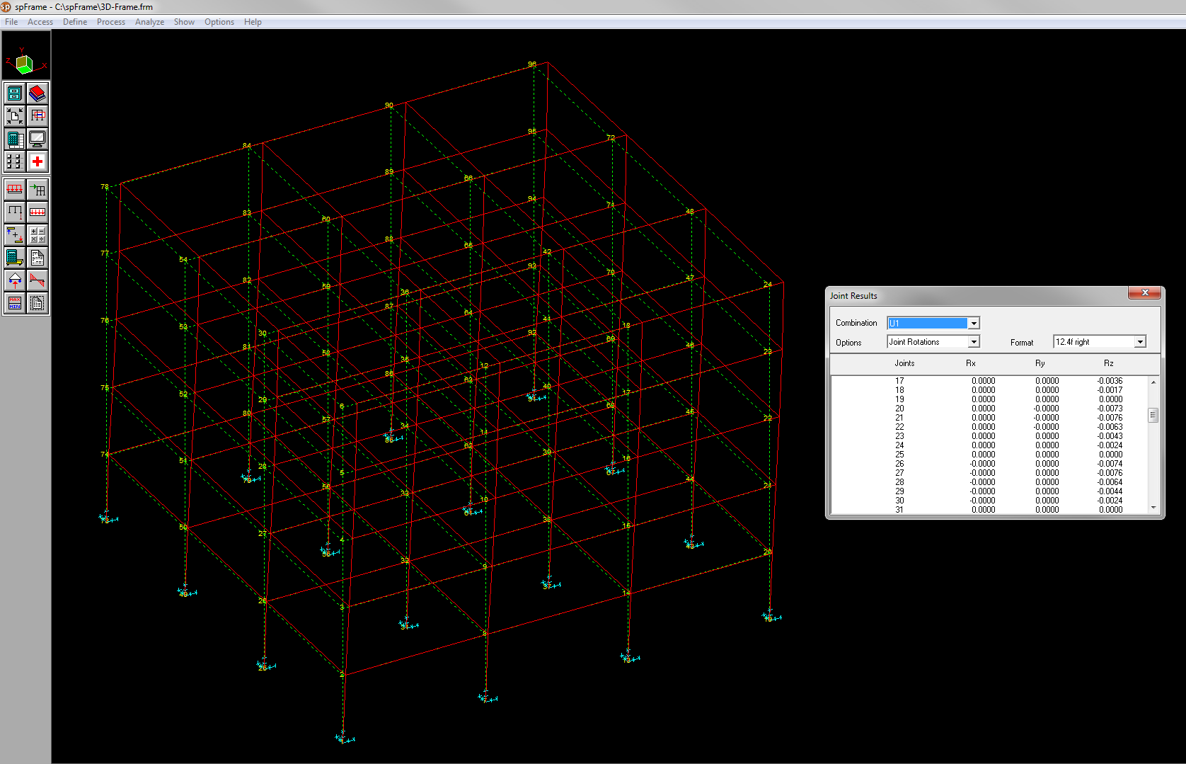
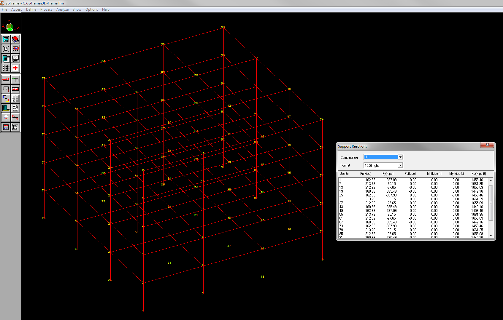
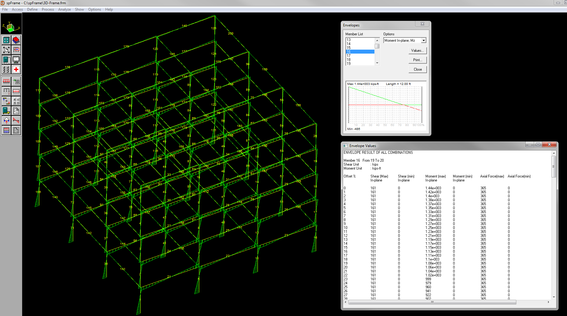
With spFrame, engineers may view all output results in text or graphical formats before printing. Output includes: joint displacements and rotations, support reactions, member end forces and moments, segmental member results (at 100 locations per member), member summary, result envelopes, and diaphragm displacements.
![]()
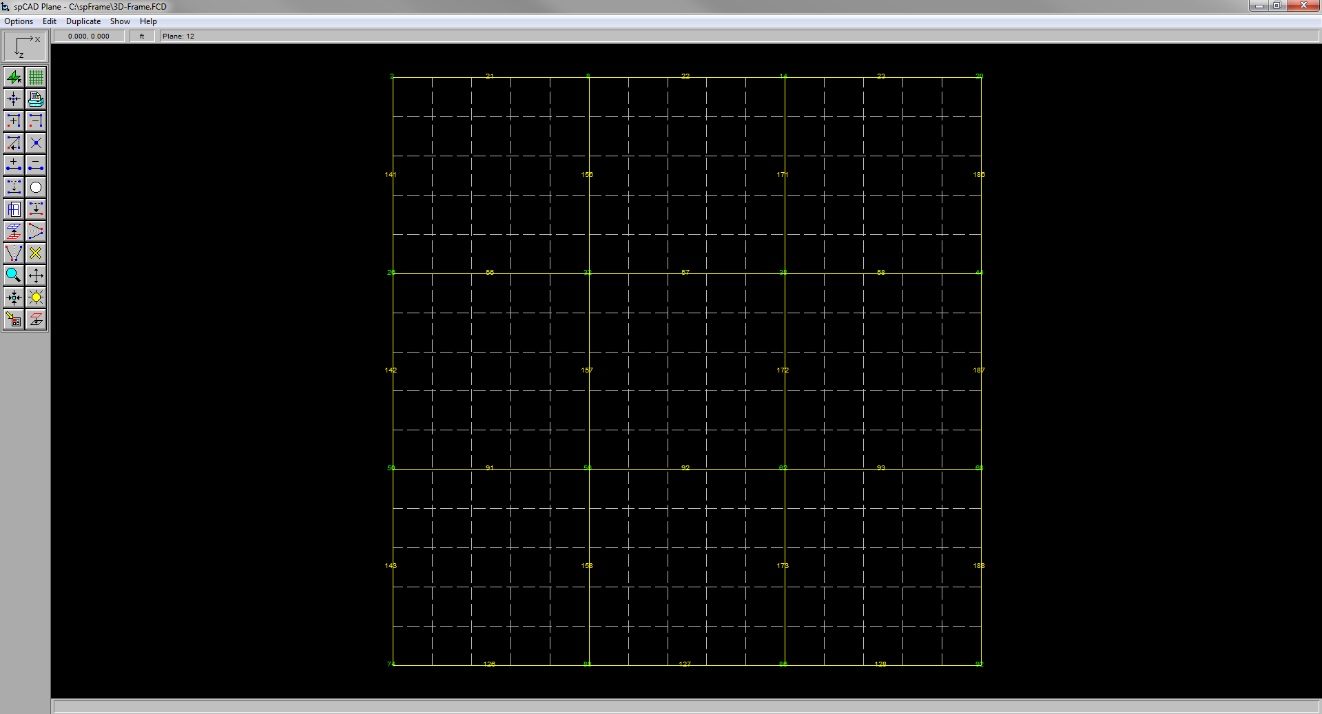
spCad, a graphical model generator for spFrame, facilitates modeling a structure by simply drawing it right on the screen. Member and joint properties, loads, and other assignments are also applied graphically through user-friendly and easy-to-use, yet powerful, interface. spCad eliminates the drudgery of manual data entry and enables fast generation of the most complicated structural models.

spFrame has a two-pass solver using the stiffness method of analysis. The first pass can be performed after the model geometry is defined. The program computes the element stiffness matrices and builds the associated global stiffness matrix of the whole structure. The element stiffness matrix is a square matrix proportional to the member degrees of freedom (e.g. a plane truss element stiffness matrix is 4 x 4, whereas a space frame element stiffness matrix is 12 x 12). The element stiffness matrix is then multiplied by the applicable transformation matrices to account for member orientation and any special corrections.
The second pass can be executed after the applied loads and the corresponding load combinations are defined. The program builds the load matrix, inverts the global stiffness matrix, builds the displacement matrices, and solves for the joint displacements, joint reactions and member end forces. Therefore, the structure can be analyzed under different sets of loads and/or load combinations without having to recalculate the stiffness matrices again.
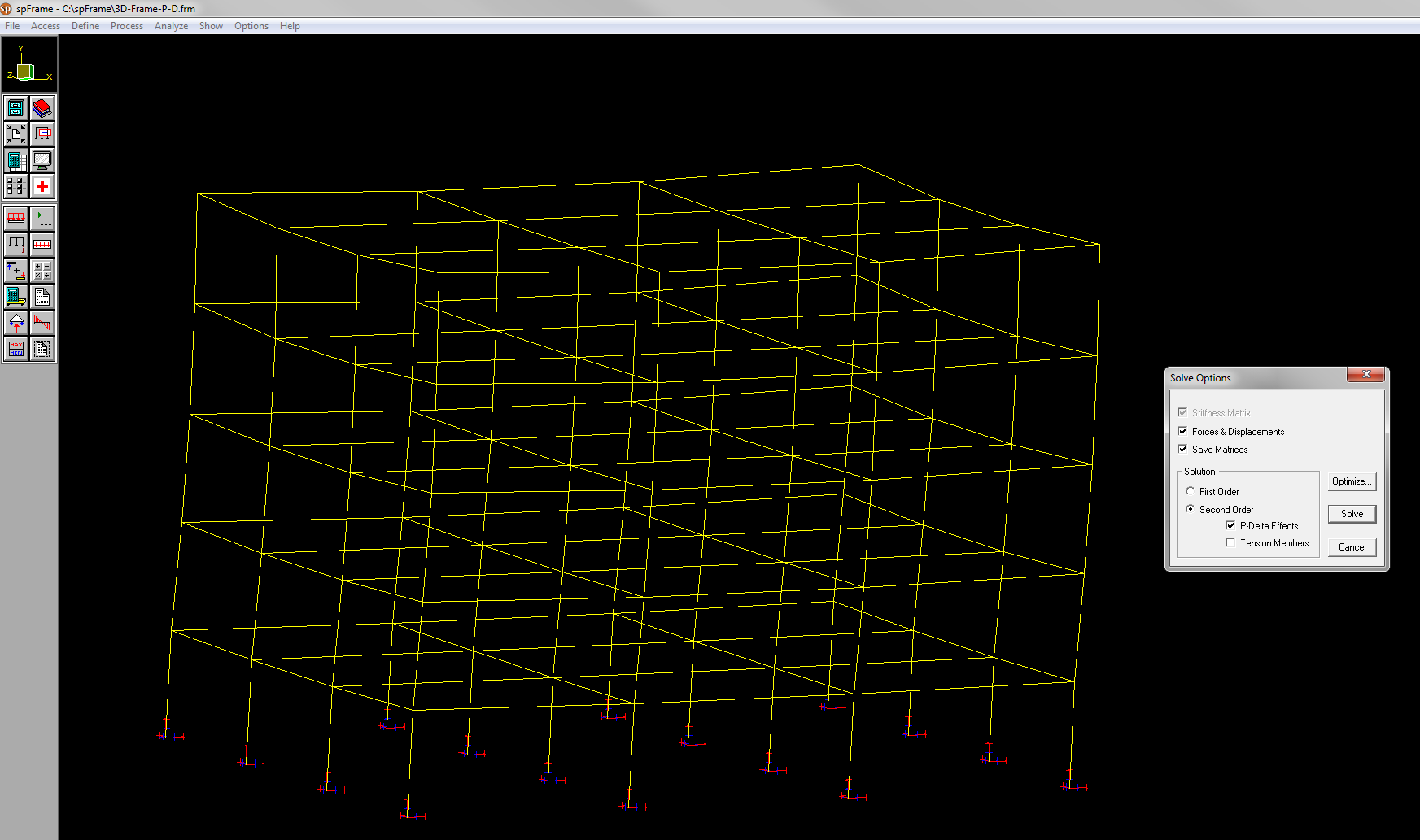
When executing the solver for the first time for a particular problem, a first-order analysis is performed and the resulting joint displacements, joint rotations, support reactions, and member end forces are computed. To compute secondary P-Δ effects or to solve for tension-only members, a second run must be executed. This second run is necessary because the solver needs some results from the first run. In a second-order analysis, members designated as tension-only members will be removed from the model if they are subjected to any compressive loads.
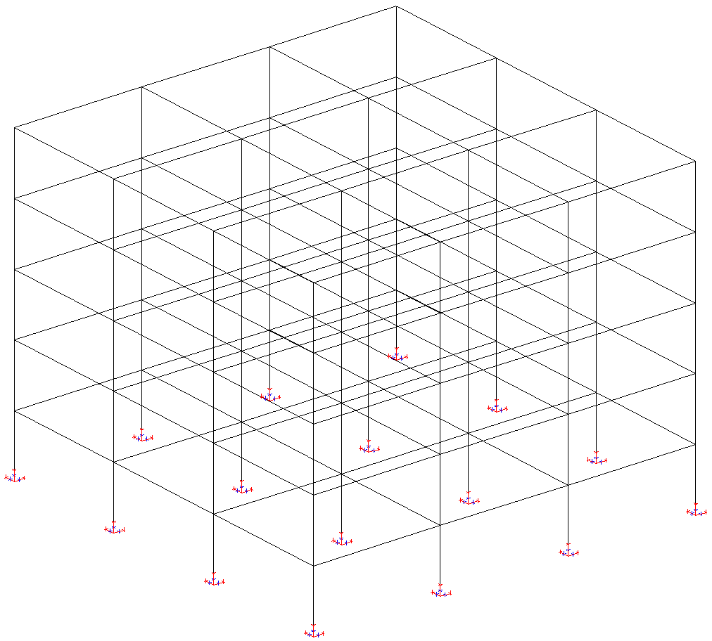
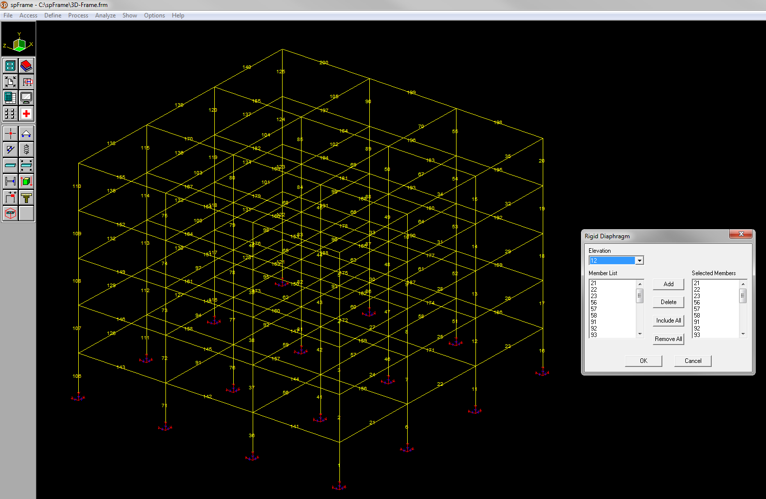
In structural analysis of buildings subject to lateral loads, concrete floor slabs are usually considered to be infinitely stiff in their own plane. This assumes that floors displace as rigid bodies and the story shears and torsional moments are distributed to the vertical members (columns and walls) in proportion to their relative stiffnesses.
Modeling of rigid diaphragms in spFrame may be done by attaching infinite in-plane stiff beams to the floor diaphragms. These members will share the same in-plane degrees of freedom and will move as a rigid body in the X-Z plane.
spFrame Program performs second-order analysis of a particular model after completing the first-order run successfully. The second order analysis may be selected under Solve Options Menu.
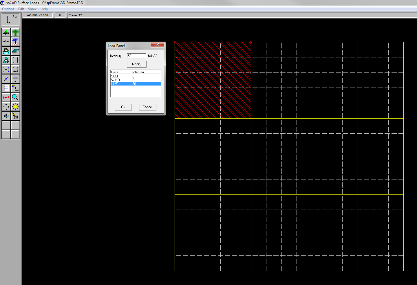
Surface Loads option of spCad enables you to draw panels spanning over members of a floor and apply area loads to these panels. Working in a specific floor plan (XZ plane), the panels are drawn graphically on the screen. A panel is a slab-like element that is attached to the members it comes in contact with.
- A panel is drawn by drawing panel nodes that are connected with straight lines to form the panel boundaries. The shape or size of a panel may be modified by moving, editing, or deleting some of its nodes.
- Openings may exist within a panel.
- By default, each member that comes in contact with a panel is attached to it. A member may be detached from a panel to exclude the panel load on it. A member that does not touch the panel cannot be attached to it.
- Panels are loaded with one uniform area load under a particular load case. The area load is applied over the entire panel.
- Only gravity loads (including self weight) may be applied on a panel. The computed member loads are applied in the negative global Y direction.
- Each panel is divided into a grid of finite square elements. The area of each finite element is computed and assigned to the member closest to it. The total area of the segments assigned to a member constitutes its tributary area.
- The member load length is the member intersection with the panel. If the panel covers a member completely, the member load length is the entire length of the member.
- The tributary area of a member multiplied by the panel load is applied uniformly over the member. No variation of the load intensity is accounted for.
- Based on the member tributary area, a live load reduction can be computed. Load reduction may be computed for beams and columns. The load reduction factors are saved with the data file to be used by spFrame when combining the analysis results.
Additional 20% discount available for multi-product bundle purchase spMats, spBeam, spColumn, spSlab, spWall, spFrame (formerly pcaMats, pcaBeam, pcaColumn, pcaSlab, pcaWall, pcaFrame). Email us at info@StructurePoint.org for more information on pricing and licensing.